Chapter 10: Quality & Acceptance
Quality standards, acceptance testing procedures, performance benchmarks, and commissioning checklists for smart agriculture environmental monitoring systems.
10.1 Quality Standards Overview
System quality in smart agriculture monitoring is defined across three dimensions: hardware quality (physical installation, environmental protection, and component grade), data quality (accuracy, completeness, and reliability of sensor measurements), and operational quality (system availability, alarm reliability, and maintenance compliance). A system that meets all three quality dimensions delivers consistent, actionable data that supports confident crop management decisions. The comparison image below illustrates the visible difference between poor-quality and high-quality sensor installations in the field.
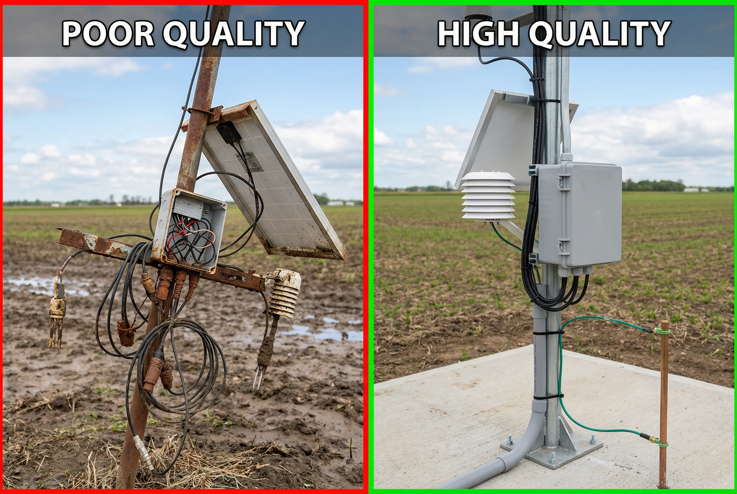
Figure 10.1: Quality Comparison — Poor Installation (left) vs. High-Quality Professional Installation (right). Key differences include cable management, enclosure sealing, mounting stability, and grounding.
10.2 Hardware Quality Acceptance Criteria
Hardware acceptance testing must be completed before system commissioning. Each item in the acceptance checklist must be verified by the commissioning engineer and documented in the acceptance report. Items marked "FAIL" must be corrected before the system is handed over to the operator.
| Acceptance Item | Acceptance Criterion | Test Method | Pass Condition |
|---|---|---|---|
| Sensor mounting stability | No movement under 10 kg lateral force | Physical push test | Zero movement, no loosening of fasteners |
| Enclosure IP rating | IP65 minimum for outdoor, IP68 for buried | Visual inspection + water spray test | No water ingress after 1-minute spray |
| Cable gland sealing | All cable entries sealed with IP-rated glands | Visual inspection | No open cable entries, glands fully tightened |
| Radiation shield orientation | T/RH sensor shield opening facing north (NH) or south (SH) | Compass check | Within ±30° of correct orientation |
| Sensor height (T/RH) | 1.5 m above ground level (WMO standard) | Tape measure | 1.5 ± 0.1 m |
| Mounting pole verticality | Pole within 2° of vertical | Spirit level | Bubble within tolerance marks |
| Grounding resistance | <10 Ω (general); <4 Ω (lightning protection zone) | Earth resistance tester | Measured value below threshold |
| SPD installation | Type 2 SPD on all power and RS-485 lines | Visual inspection | SPD present, correctly wired, indicator green |
| Cable labeling | All cables labeled at both ends with sensor ID | Visual inspection | All cables labeled, labels legible |
| Tamper seals | Tamper-evident seals on all enclosure screws | Visual inspection | Seals present and intact |
10.3 Data Quality Acceptance Criteria
Data quality acceptance testing verifies that the system produces accurate, complete, and reliable measurements under real field conditions. The test must be conducted over a minimum 72-hour period following hardware acceptance. All sensors must be calibrated before data quality testing begins.
| Parameter | Accuracy Requirement | Completeness | Test Duration | Acceptance Threshold |
|---|---|---|---|---|
| Air Temperature | ±0.5°C vs. reference thermometer | ≥99% | 72 hours | All readings within ±0.5°C; <1% missing data |
| Relative Humidity | ±3% RH vs. reference | ≥99% | 72 hours | All readings within ±3% RH; <1% missing data |
| Soil VWC | ±3% VWC (calibrated) | ≥98% | 72 hours | Calibrated readings within ±3% vs. gravimetric sample |
| CO₂ Concentration | ±50 ppm + 3% of reading | ≥99% | 72 hours | Span check with reference gas within tolerance |
| Wind Speed | ±0.5 m/s (0–5 m/s); ±10% (5–50 m/s) | ≥98% | 72 hours | Cross-check with adjacent reference station |
| Rainfall | ±5% of total measured | ≥99% | First rain event | Tipping bucket count vs. manual rain gauge |
| Dissolved Oxygen | ±0.2 mg/L vs. Winkler titration | ≥98% | 72 hours | Field comparison with portable DO meter |
| pH | ±0.1 pH unit vs. reference | ≥98% | 72 hours | Buffer solution verification at pH 4.0, 7.0, 10.0 |
10.4 System Performance Acceptance Criteria
System performance acceptance verifies that the complete system — from sensor to cloud dashboard — meets the operational requirements specified in the design document. Performance testing must be conducted with the system under normal operating conditions, including at least one simulated network outage to verify edge buffering and alarm delivery.
| Performance Metric | Target | Minimum Acceptable | Test Method |
|---|---|---|---|
| Data reporting interval | As designed (5–15 min) | Within ±10% of target | Log timestamp analysis over 24 hours |
| Cloud data latency | <60 seconds | <300 seconds | Timestamp comparison: sensor vs. cloud receipt |
| Alarm delivery time | <2 minutes from threshold breach | <5 minutes | Trigger test alarm, measure delivery time |
| System availability | ≥99.5% over 30 days | ≥98% over 30 days | Uptime monitoring log analysis |
| Edge buffer recovery | 100% data recovery after 24h outage | ≥95% data recovery | Simulate 24h network outage, verify data upload |
| Dashboard load time | <3 seconds (10 sensors) | <8 seconds | Browser developer tools timing |
| Mobile app functionality | All alarms visible on mobile | Critical alarms visible | Functional test on iOS and Android |
10.5 Acceptance Report Requirements
A formal acceptance report must be prepared and signed by both the installation contractor and the system owner before the warranty period begins. The report serves as the baseline reference for all future maintenance and performance evaluations. The report must include the following sections.
- Project information: site name, GPS coordinates, installation date, contractor details
- Hardware acceptance checklist: all items from Section 10.2 with pass/fail status and photographs
- Sensor calibration certificates: copies of calibration records for all sensors
- Data quality test results: 72-hour data log with accuracy analysis vs. reference instruments
- System performance test results: all metrics from Section 10.4 with measured values
- Outstanding items list: any items requiring follow-up action with responsible party and due date
- Signatures: commissioning engineer, site supervisor, and system owner
Warranty Activation: The warranty period for all hardware components begins on the date of signed acceptance, not the date of delivery. Ensure all acceptance tests are completed and the report is signed before the warranty clock starts. Unsigned acceptance reports void manufacturer warranties in most jurisdictions.