Chapter 8: Tools & Accessories
Complete accessories list, installation tools, calibration equipment, spare parts inventory, and procurement guidance for smart agriculture monitoring system deployment.
8.1 Accessories & Tools Overview
A successful smart agriculture monitoring system installation requires not only the core sensing and gateway hardware, but also a comprehensive set of accessories, installation tools, and calibration equipment. Inadequate accessory planning is a common cause of project delays and cost overruns. The checklist image below provides a visual overview of all 16 standard accessory and tool categories required for a complete system deployment.
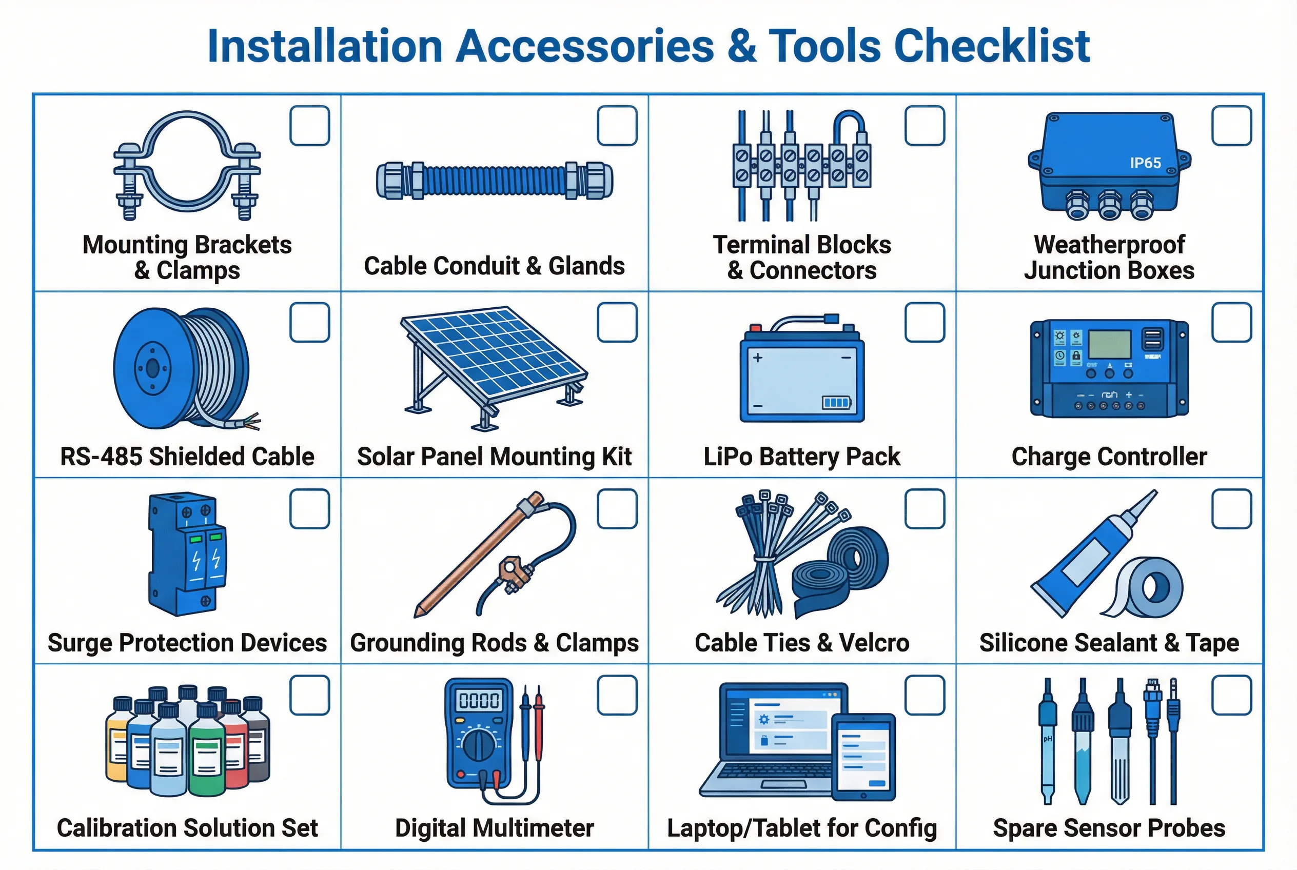
Figure 8.1: Installation Accessories & Tools Checklist — 16 Standard Categories for Smart Agriculture Monitoring System Deployment
8.2 Complete Accessories Bill of Materials
The table below provides a comprehensive bill of materials (BOM) for a typical smart agriculture monitoring deployment covering 5–10 monitoring nodes with one central gateway. Quantities should be adjusted based on the specific deployment scale. Items marked "Required" are essential for all deployments; "Optional" items enhance functionality or serviceability; "Spare" items are recommended to maintain on-site for rapid repair.
| Category | Item | Specification | Qty (per 10 nodes) | Status | Notes |
|---|---|---|---|---|---|
| Mechanical | Sensor mounting brackets | Stainless steel, adjustable angle, 32–60 mm tube clamp | 20 sets | Required | 2 per node (sensor + solar panel) |
| Mechanical | Mounting poles / masts | Galvanized steel, 50 mm OD, 2–3 m length | 10 pcs | Required | 1 per field node |
| Mechanical | Ground anchors / base flanges | Concrete anchor or driven ground spike | 10 sets | Required | Match pole diameter |
| Electrical | RS-485 shielded cable | 2-core + shield, 24 AWG, outdoor UV-rated jacket | 500 m | Required | 50 m average per node run |
| Electrical | Weatherproof junction boxes | IP65, 150×100×70 mm, ABS with cable glands | 10 pcs | Required | 1 per node for cable splices |
| Electrical | Terminal blocks (DIN rail) | Phoenix Contact or equivalent, 2.5 mm², 10-way strips | 5 strips | Required | For gateway enclosure wiring |
| Electrical | Cable glands (PG type) | PG7, PG9, PG11 assorted, IP68 rated | 50 pcs | Required | 5 per junction box |
| Electrical | Surge protection devices (SPD) | Type 2, 12V DC, RS-485 line, DIN rail mount | 10 pcs | Required | 1 per node communication line |
| Power | Solar panel mounting kit | Adjustable tilt bracket, 30–60° range, stainless steel | 10 sets | Required | For all solar-powered nodes |
| Power | Battery enclosure box | IP65, vented, lockable, sized for 20–40 Ah battery | 10 pcs | Required | Outdoor battery protection |
| Power | MPPT charge controller | 10–20A, 12/24V auto, LCD display | 10 pcs | Required | 1 per solar-powered node |
| Sealing | Silicone sealant (neutral cure) | Clear, UV-resistant, -40°C to +200°C | 5 tubes | Required | Seal all cable entry points |
| Sealing | Self-amalgamating tape | 25 mm × 3 m rolls, weatherproof | 10 rolls | Required | Connector and cable joint sealing |
| Fasteners | Stainless steel cable ties | 4.6 mm × 200 mm, 316 SS | 200 pcs | Required | UV and corrosion resistant |
| Grounding | Ground rods | 1.5 m copper-clad steel, 14 mm diameter | 10 pcs | Required | 1 per node with lightning protection |
| Grounding | Ground clamps and lugs | Copper, 16 mm² cable compatible | 20 pcs | Required | For bonding mast to ground rod |
| Tools | Digital multimeter | True RMS, CAT III 600V, RS-485 voltage measurement | 1 pc | Required | Essential for commissioning and fault finding |
| Tools | Laptop / tablet (config) | Windows 10+, USB port, Modbus config software installed | 1 pc | Required | For gateway configuration and sensor addressing |
| Tools | Crimping tool set | RJ45, ferrule crimper, wire stripper combo | 1 set | Required | For cable termination |
| Calibration | pH calibration solution set | pH 4.0, 7.0, 10.0 buffer solutions, 250 mL each | 1 set | Optional | Required for water quality sensor deployments |
| Calibration | DO calibration kit | Zero-oxygen solution + air-saturated water method | 1 set | Optional | Required for aquaculture deployments |
| Calibration | CO₂ reference gas cylinder | 1,000 ppm CO₂ in N₂, 1L disposable | 2 pcs | Optional | For CO₂ sensor span calibration verification |
| Spare Parts | Spare temperature/humidity sensors | Same model as installed sensors | 2 pcs | Spare | 20% spare ratio recommended |
| Spare Parts | Spare LoRa field nodes | Fully configured, same firmware version | 1 pc | Spare | For rapid swap during failures |
| Spare Parts | Spare batteries (LiFePO4) | Same capacity and chemistry as installed | 2 pcs | Spare | Replace proactively at 3-year mark |
| Spare Parts | Spare RS-485 cable (50 m) | Same specification as installed cable | 1 reel | Spare | For emergency cable replacement |
8.3 Calibration Equipment Requirements
Sensor calibration is a recurring maintenance task that requires specific equipment. The calibration equipment must be appropriate for the sensor types deployed, properly stored between uses, and replaced or recertified at the intervals specified by the calibration solution manufacturer. Field calibration should always be performed by trained personnel following the sensor manufacturer's calibration procedure.
Calibration Record Keeping: All calibration activities must be documented with date, technician name, reference solution lot number, pre-calibration reading, post-calibration reading, and acceptance criteria. These records are required for ISO 9001 compliance and regulatory reporting in many jurisdictions.