Chapter 11: Installation & Debugging
Step-by-step installation procedures, sensor placement requirements, gateway configuration, system commissioning, and debugging protocols for smart agriculture monitoring deployments.
11.1 Installation Requirements Overview
Correct installation is the single most important factor in long-term system reliability. The majority of field failures in the first year of operation are attributable to installation errors rather than hardware defects. The image below shows a professional outdoor field installation, demonstrating correct pole mounting, solar panel orientation, cable management, and gateway enclosure installation in an open agricultural field.
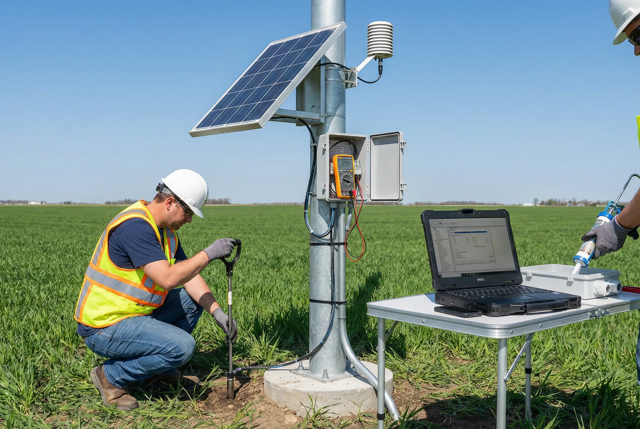
Figure 11.1: Installation Requirements — Professional Field Installation Showing Correct Pole Mounting, Solar Panel Orientation, Cable Management, and Commissioning Procedure in Open Agricultural Field
For greenhouse and indoor farming environments, the installation requirements differ significantly from open-field deployments. The image below shows a professional greenhouse installation, demonstrating sensor placement at canopy height, cable routing along greenhouse frame, edge gateway wall mounting, and the use of calibration equipment during commissioning.
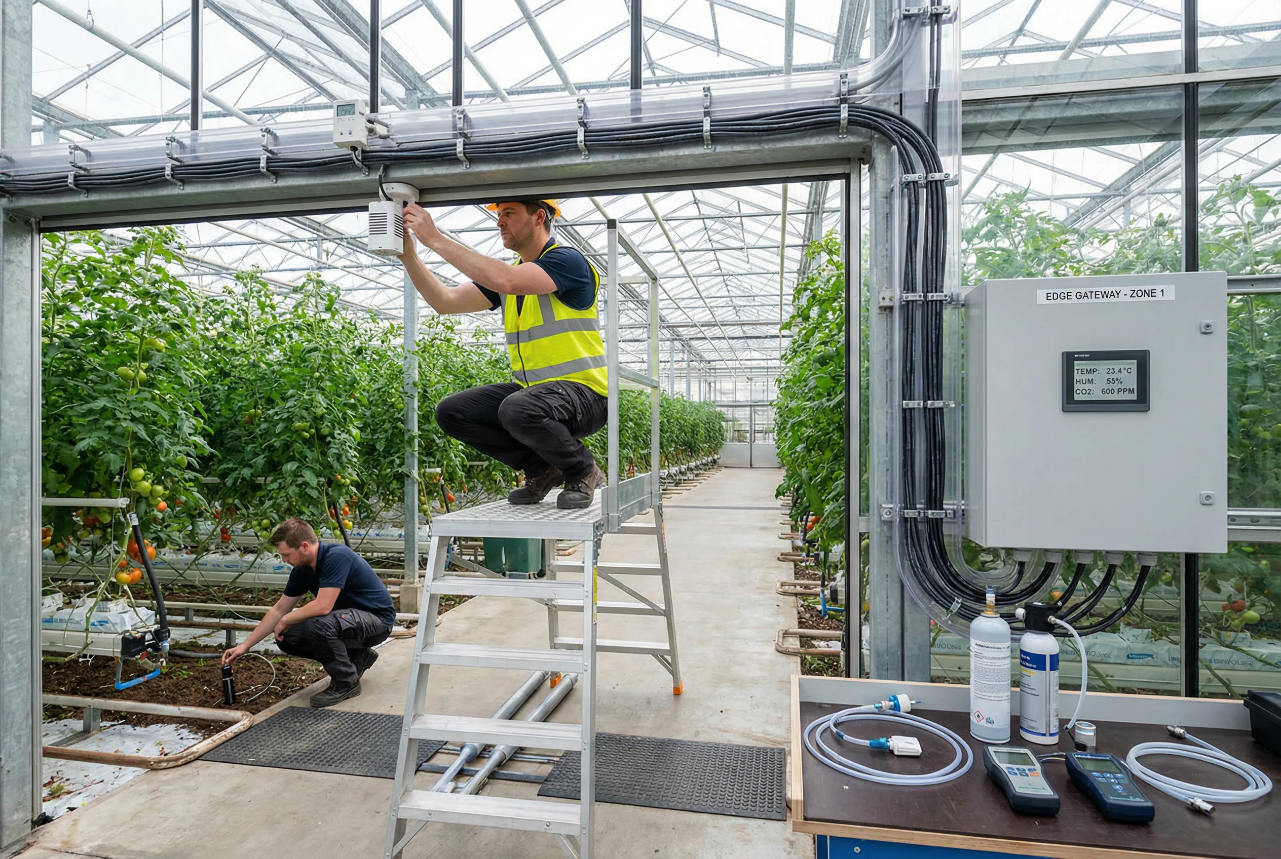
Figure 11.2: Greenhouse Installation Requirements — Sensor Placement at Canopy Height, Cable Management Along Frame, Edge Gateway Enclosure, and Calibration During Commissioning
11.2 Pre-Installation Site Survey Requirements
A thorough site survey must be completed before any hardware is ordered or installation begins. The site survey identifies potential obstacles, confirms communication coverage, verifies power availability, and establishes the exact sensor placement coordinates. Skipping the site survey is the most common cause of post-installation rework and cost overruns.
| Survey Item | What to Measure / Verify | Tool Required | Decision Outcome |
|---|---|---|---|
| LoRa signal coverage | RSSI and SNR at each planned node location | LoRa field tester or smartphone app | Confirm gateway placement or add repeater |
| 4G signal strength | Signal bars and data speed at gateway location | Smartphone with carrier SIM | Confirm carrier, select antenna type |
| Solar irradiance / shading | Check for tree/building shadows at 9am, 12pm, 3pm | Site visit at different times | Confirm panel orientation and tilt angle |
| Soil type at sensor locations | Soil texture (sandy/loam/clay) for VWC calibration | Soil probe, texture test | Select appropriate soil calibration curve |
| Flood risk assessment | Historical flood levels, drainage patterns | Site inspection, local records | Set minimum mounting height above flood level |
| Power availability | Grid power at gateway location (voltage, phase) | Voltmeter | Confirm power supply specification or solar sizing |
| Cable routing path | Measure cable run lengths, identify obstacles | Measuring tape, site map | Finalize cable BOM quantities |
| Lightning risk zone | Identify highest structures within 500m radius | Site inspection | Determine lightning protection level required |
11.3 Step-by-Step Installation Procedure
The following installation sequence must be followed for all outdoor field node installations. Deviating from this sequence can result in safety hazards, rework, or system failures. Each step must be signed off by the lead installer before proceeding to the next step.
11.4 Common Debugging Issues and Solutions
The table below provides a structured troubleshooting guide for the most common issues encountered during system commissioning. For each issue, the probable cause and step-by-step diagnostic procedure are provided to minimize troubleshooting time.
| Symptom | Probable Cause | Diagnostic Steps | Solution |
|---|---|---|---|
| Sensor shows "no response" in gateway | Wrong Modbus address, wiring fault, or power issue | 1. Check power LED on sensor; 2. Measure RS-485 voltage (should be 0.2–6V differential); 3. Verify Modbus address matches gateway config | Correct address, fix wiring, check power supply |
| Temperature reading 10–30°C too high | Radiation shield missing or incorrectly oriented | 1. Inspect radiation shield installation; 2. Check shield orientation (not facing direct sun); 3. Compare with reference thermometer in shade | Install/reorient radiation shield, add solar shield |
| LoRa node intermittent connection | RF path obstruction or low battery | 1. Check RSSI and SNR in gateway logs; 2. Measure battery voltage; 3. Walk the RF path for new obstructions | Raise antenna height, reposition node, replace battery |
| No data on cloud dashboard | 4G network issue, MQTT credentials wrong, or firewall | 1. Check 4G signal bars on gateway; 2. Verify MQTT broker address and credentials; 3. Check cloud platform status page | Correct MQTT config, check SIM data plan, contact ISP |
| Soil VWC reading stuck at 0% or 100% | Probe not fully inserted or air gap around probe | 1. Remove probe and inspect for damage; 2. Re-insert probe ensuring full contact with soil; 3. Verify probe cable is not damaged | Re-install probe with proper soil contact, replace if damaged |
| Alarms not delivered to mobile | Push notification disabled or alarm rule misconfigured | 1. Check mobile app notification permissions; 2. Verify alarm threshold values in platform; 3. Test with manual alarm trigger | Enable notifications, correct threshold values, re-test |
Safety Warning: Never work on live electrical connections in wet conditions. Always de-energize the power supply before opening enclosures or modifying wiring. Agricultural environments present elevated electrical hazard risk due to moisture, conductive soil, and metallic structures.